This procedure is specific to the 2004 Montana, but may be useful for Ventures, Silhouettes, and other model years of GM minivans. A couple of dash lights burned out and the tachometer, speedometer, temperature and fuel gauges were reading unreliably. The standard repair is to replace the instrument cluster, but here we describe replacing individual bulbs and stepper motors, and in the process how to get the dash and center console apart.
Tools required are #2 posi-drive, or in a pinch a cross or philips, screwdriver, 7mm socket driver, and a 13mm socket wrench.
Lower Section of Center Console
The lower center console cover or bezel holds the 12v power plugs and covers the DVD if equipped.
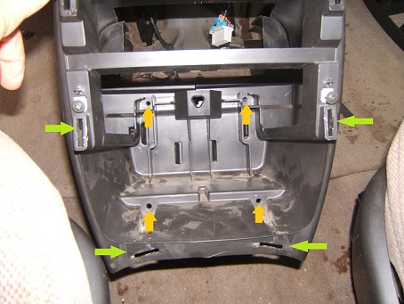
- Pull the bezel rearward off of 4 clips. Green arrows in Fig. 1 locate the holes these clips insert into
- Disconnect power supply/cigarette lighter wiring connectors by squeezing the gray side to depress a gray clip inside the hole it is installed in. Note whether any of the 4 bezel clips ended up inside the lower console and will need to be retrieved later.
- Remove DVD held by 2 screws, 1 each side of player. Move it rearward and disconnect wiring connector. You might want to put the screws back in their holes for safe keeping while disassembled
- Lowest section mounted with 4 screws facing rearward inside the section itself. Orange arrows in Fig. 1 indicate locations of the 4 screws
- Wiring harness for DVD may be clipped to the lower console just above where the back of the DVD case was. Can be seen from the floor.
- Move both seats back all the way. Then move the lower console section rearward and upward between the seats
Upper Section of Center Console
The upper section of the center console includes the radio, heater A/C controls, and the cup holder. This holder and the bezel surrounding the radio come off as one piece.
- The cup holder cover may be removed to provide easier access to two bezel screws, Remove this cover with 2 screws downward facing, 1 each side along the bottom of the cover
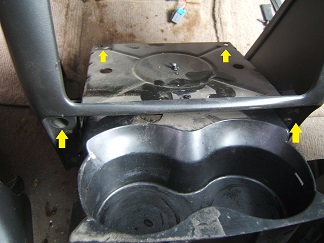
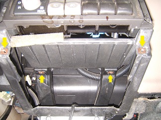
- Remove the 4 screws that secure the cup holder/bezel piece, Fig. 2 and 3, Two screws are rearward facing and were behind the cup holder cover, 1 each side of cup holder.
- Extend the cup holder ready to set a cup into, then find the 2 hidden screws facing downward forward of the opened cup holder, Fig. 2, The bezel/cup holder should now be swinging freely.
- Swing cup holder/bezel assembly rearward and upward on clips along the top edge that hook into the cluster bezel just below the center heater A/C outlets.
Heater controls, radio are now ready for further removal if needed. See Heater Control Switches or Bulbs for further details.
Left Lower Dash and Instrument Cluster
- nsulated panel that covers the horizontal space between the knee bolster and the firewall. This delicate panel is held in place by 2 posts on the firewall and 2 plastic push pins inserted into the lower edge of the knee bolster
- Knee bolster is the painted panel your knees would hit below the steering column. It is secured by 3 downward facing screws along the lower edge and 4 bezel clips upper edge (2 each side of steering column)
- Lower the steering column on the two 13mm nuts that support it upward, to near the end of their threads.
- instrument panel bezel is secured by 8 bezel clips. Pull bezel rearward to release clips. Apply parking brake, turn key on, select low gear (shifter down), move bezel rearward over the steering wheel upper edge first.
- instrument cluster assembly is secured by 4 screws facing the driver. With these screws removed, rotate the rear of the cluster downward about 90 degrees. Disconnect 2 wiring connectors, then remove gauge cluster.
Disassemble Instrument Cluster
- Separate the 4 clear cluster cover clips, by hand if possible. Lift the clear cover upward keeping the gauges facing upward. Lift out push button shaft & spring
- Gauge pointers should be pulled straight off their motor needles perpendicular to the cluster board
- Rear black cluster panel secured by 5 clips. By hand again, lower 2 first separating the cover a little, then upper 3, gentle with the circuit board
- Pull wiring connector out of socket on the information center, the other end is soldered to the circuit board
- Replace all motors and gauge back-light incandescent bulbs at this time, or disassemble and reassembly in the near future. The high-beam indicator bulb might be a safe bet to leave for later replacement.
- Reverse the above steps to reassemble